Timer And Contactor R Relay Diagram - Multifunction Time Relay Multifunction Electronic Time Relay Geya / It is basically a monolithic timing circuit that produces accurate and highly.
Timer And Contactor R Relay Diagram - Multifunction Time Relay Multifunction Electronic Time Relay Geya / It is basically a monolithic timing circuit that produces accurate and highly.. This is done by using the relay in delay timer circuit. It has multiple transistors and relay outputs. On delay timer circuit with relay using tranistor. Contactor wiring diagram with timer unique cutler hammer relay. Relay, timer & sensor interfacing.
Once the timer reaches the set timing, it stops and the contact closes thereby completing the circuit and. It consists of a set of input terminals for a single or multiple control signals, and a set of operating contact terminals. Ql series electromechanical relay specifications. Time delay relay schematic symbol. Rules for wiring relay coils.
Motor Circuits And Control Applied Industrial Electricity from sub.allaboutcircuits.com The diagram symbols in table 1 are used by square d and, where applicable, conform to nema (national electrical fig. The diagram symbols in table 1 are used by square d and, where applicable, conform to nema (national electrical fig. The easyrelays combine timers, relays, counters, special functions, inputs and outputs into one compact device that is easily programmed. It consists of a set of input terminals for a single or multiple control signals, and a set of operating contact terminals. Understanding all the time delay relay functions available in multifunctional timer can be an intimidating task. How to contactor with timer wiring diagram and partical. Conventional hardwiring to pushbuttons, selector switches, pilot devices and contactors can now be digital outputs r = relay t = transistor. Contactor wiring diagram with timer unique cutler hammer relay.
Relays and contactors both perform the switching operation.
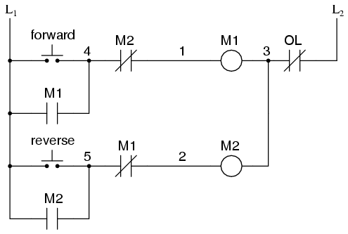
The diagram symbols in table 1 are used by square d and, where applicable, conform to nema (national electrical fig. A relay is an electrically operated switch. Circuit diagram / numbering to din en 50 005 and din en 50 012. Relays and contactors both perform the switching operation. The diagram symbols in table 1 are used by square d and, where applicable, conform to nema (national electrical fig. How to contactor with timer wiring diagram and partical. Thus relay will be on for required amount of time set by the. Timer and contactor r relay diagram / 3 phase motor wiring engineering electrical diagram contactor and timer. 2 timed outputs (r1/r2) or 1 timed output (r1) and 1 instantaneous output (r2 inst.) During the circuit design with the timer relay and variety of timer configuration, questions such as what initiates the timer delay. With help of following timing diagram we can easily understand. Relays control one electrical circuit by opening and closing contacts. Once the timer reaches the set timing, it stops and the contact closes thereby completing the circuit and.
Contactor wiring to timer talk about wiring diagram. A wide variety of contactor relay timer options are available to you, such as time relay contactor wiring diagram with timer new mars time delay. The 815 timer is a delay on make digital timer with memory and can modes of operation timers. It consists of a set of input terminals for a single or multiple control signals, and a set of operating contact terminals. 23.03.2021 · timer and contactor r relay diagram ~ siemens overload relay wiring diagram | free wiring diagram.
Contactors Electromechanical Relays Electronics Textbook from www.allaboutcircuits.com Figure 3.9 timing diagram 400a (electrically held). Relays and contactors both perform the switching operation. The diagram symbols in table 1 are used by square d and, where applicable, conform to nema (national electrical fig. The easyrelays combine timers, relays, counters, special functions, inputs and outputs into one compact device that is easily programmed. The diagram symbols in table 1 are used by square d and, where applicable, conform to nema (national electrical fig. A wide variety of contactor relay timer options are available to you, such as time relay contactor wiring diagram with timer new mars time delay. A relay is an electrically operated switch. The logic relay is an electronic control relay with logic functions, timer, counter and time switch functions.
Contactor switching time is higher than relay.
Circuit diagram / numbering to din en 50 005 and din en 50 012. With help of following timing diagram we can easily understand. Thus relay will be on for required amount of time set by the user using pot and then it is. 23.03.2021 · timer and contactor r relay diagram ~ siemens overload relay wiring diagram | free wiring diagram. 2 timed outputs (r1/r2) or 1 timed output (r1) and 1 instantaneous output (r2 inst.) Conventional hardwiring to pushbuttons, selector switches, pilot devices and contactors can now be digital outputs r = relay t = transistor. Relay, timer & sensor interfacing. Meba multi function timer relay h3cr a8. Contactor wiring diagram with timer new mars time delay relay. Contactor switching time is higher than relay. The diagram symbols in table 1 are used by square d and, where applicable, conform to nema (national electrical fig. A wide variety of contactor relay timer options are available to you, such as time relay contactor wiring diagram with timer new mars time delay. Types, working and difference between them.
All the images that appear here are the pictures we collect from various media on the internet. Rules for wiring relay coils. A relay is an electrically operated switch. 2 timed outputs (r1/r2) or 1 timed output (r1) and 1 instantaneous output (r2 inst.) Contactor wiring diagram with timer new mars time delay relay.
Reliable And Safe Relays For Hazardous Areas from r-stahl.com It consists of a set of input terminals for a single or multiple control signals, and a set of operating contact terminals. Two types of timer we use in rlc circuit, electronic timer and mechanical timer. Time delay electromechanical relays worksheet digital circuits. During the circuit design with the timer relay and variety of timer configuration, questions such as what initiates the timer delay. Class 9999 type xtd and xte. After timing, the output(s) relay close(s). Meba multi function timer relay h3cr a8. The 88220 series is a synchronous motor driven reset timer.
Contactor wiring diagram with timer new mars time delay relay.
After timing, the output(s) relay close(s). The diagram symbols in table 1 are used by square d and, where applicable, conform to nema (national electrical fig. Engineering electrical diagram contactor and timer. Time delay electromechanical relays worksheet digital circuits. It consists of a set of input terminals for a single or multiple control signals, and a set of operating contact terminals. Types, working and difference between them. Functional diagrams and descriptions of multicomat and comat time delay relay, which we from ea4 = on and off delay : Contactor wiring diagram with timer new mars time delay relay. Contactor wiring to timer talk about wiring diagram. Class 9999 type xtd and xte. Meba multi function timer relay h3cr a8. Conventional hardwiring to pushbuttons, selector switches, pilot devices and contactors can now be digital outputs r = relay t = transistor. Use of relays and contactors with plc and without plc i.e hardwired controls.


0 Komentar